html slideshow by WOWSlider.com v7.7


WM Diaphragm Valve
Rolling Stone Idler
Valves
Locomotives
Pumps

We specialize in the manufacturing, repairing and designing valves, locomotives and mining equipment.

Tel: 011 412 4536
Cell: 082 821 1910
Email: info@minetrack.co.za
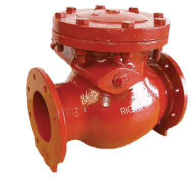
SLAMMING: Swing Check Reflux Valves are subject to slamming on rapid reversal of flow. Valve doors may be balanced by using a counter weight and lever attached to the hinge shaft. It is recommended that all sizes of high pressure reflux valves are fitted with counter weight or hydraulic dampers to regulate speed of closing.
Bypasses Valve sizes 200mm and larger may be fitted with bypass assemblies to drain the pipeline downstream of the main valve or in the open position, to relieve surge pressures.
Specifications The illustrations in this catalogue are subject to modification without notice. Valves are rated 1.6 MPa, 2.5 MPa and 40 MPa working pressure, each valve is subjected to hydraulic pressure test on body and door, without leakage, before leaving the factory.
Materials of construction (Minimum Specifications)
| Component | Specification |
| Body | Speriodal Graphite Iron (SG) |
| Cover | SG 42 & 50 |
| Door | SG 42 & 50 |
| Hinge Shaft | EN 57 Stainless Steel |
| Seat Faces | Stainless Steel appropriate to service |
| Extras Available | Lever and counterweight. |
SIZE |
BODY |
DOOR |
| 50mm - 300mm (Fig. 5-510/40) | 6.4 MPa | 4.0 MPa |
| 50mm - 300mm (Fig. 10/16/25) | 1.6/2.5/4.0 MPa | 10/16/25 MPa |
The table below indicates head loss in kPa across Right pattern swing check valves mounted in horizontal pipelines, with door shafts supported in low friction bearings and without counterweight or other damping devices affecting movement of the doors. Head loss is indicated at various fluid velocities through the valves of clean water at 200C. The minimum head loss across the valves required to hold the doors in the open position averages 3.5 kPa in all sizes.
SIZE |
No. OF DOORS |
AT 2M/S |
AT 2.5 M/S |
AT 3.0 M/S |
AT 3.5 M/S |
| 50 | 1 | 4.4 | 7.0 | 10.0 | 13.5 |
| 80 | 1 | 4.4 | 7.0 | 10.0 | 13.5 |
| 100 | 1 | 4.4 | 7.0 | 10.0 | 13.5 |
| 150 | 1 | 4.4 | 7.0 | 10.0 | 13.5 |
| 200 | 1 | 4.4 | 7.0 | 10.0 | 13.5 |
| 250 | 1 | 4.4 | 7.0 | 10.0 | 13.5 |
| 300 | 1 | 4.2 | 6.6 | 9.5 | 13.5 |
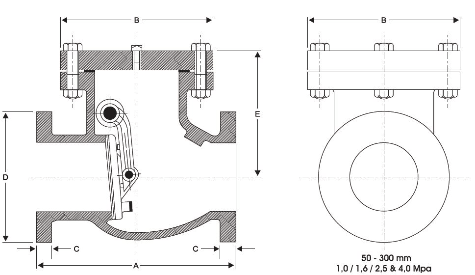
Size |
1.0/1.6/2.5 MPa SERIES |
4.0 MPa SERIES |
||||||||||
A |
B |
C |
D |
E |
MASS KG |
A |
B |
C |
D |
E |
MASS KG |
|
| 50 | 230 | 172 | 20 | 165 | 115 | 16 | 230 | 172 | 20 | 165 | 140 | 19 |
| 80 | 305 | 229 | 22 | 200 | 195 | 30 | 305 | 229 | 24 | 200 | 195 | 36 |
| 100 | 355 | 247 | 24 | 220 | 210 | 45 | 255 | 240 | 24 | 235 | 210 | 54 |
| 125 | 410 | 318 | 26 | 250 | 245 | 65 | - | - | - | - | - | - |
| 150 | 455 | 343 | 26 | 285 | 264 | 66 | 450 | 343 | 28 | 300 | 264 | 125 |
| 200 | 535 | 420 | 30 | 340 | 318 | 131 | 636 | 420 | 34 | 375 | 298 | 180 |
| 250 | 635 | 461 | 32 | 405 | 356 | 226 | 635 | 480 | 38 | 450 | 356 | 290 |
| 300 | 760 | 521 | 32 | 460 | 400 | 303 | 760 | 495 | 42 | 515 | 380 | 400 |
